Cookie Consent by Free Privacy Policy website

Sonderanwendungen MA-LC MA-LCM


PDF-Datenblatt herunterladen

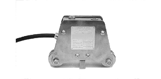
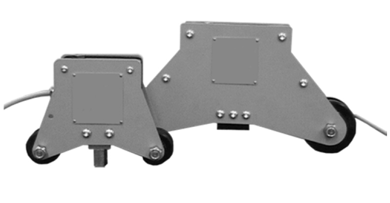
MECHANISCHER LASTBEGRENZER

Die Lastbegrenzer der Baureihe MA-LC werden mit einem einfachen Vorgang am festen Seil angebracht.

Die komplette Serie deckt eine Reihe von Standardanwendungen bis 10.000 kg am Seilzug mit einer oder zwei Eingriffsschwellen ab.

Für verschiedene Anwendungen werden Modelle mit mehr Eingriffsschwellen und höheren Nennlasten auf Anfrage hergestellt.

Die Grundmodelle sind pulverbeschichtet und mit verzinkten Teilen versehen. Bei der Installation im Außenbereich oder bei Exposition gegenüber besonders korrosiven Medien werden die Modelle komplett aus Edelstahl und mit explosionsgeschützten Endschaltern gefertigt


  • Maximale elektrische Belastung: 250V / 15A
  • Mechanische Lebensdauer: 3.000.000 Betriebszyklen
  • Isolationsklasse (IP): Lastbegrenzer IP 64 – Sicherheitsendschalter IP 67
  • Betriebstemperatur: -20° bis +50°
  • Standard Kabellänge: 4m

Installations und Bedienungsanleitung herunterladen


Zoom Zur Vergrößerung auf das Bild klicken
Sonderanwendungen MA-LC MA-LCM Sonderanwendungen MA-LC MA-LCM Montaggio
Analog Output

Technische Spezifikationen

AusgangssignalWahlweise 0-10 V oder 4-20 mA
Betriebstemperatur-20 / +50°C (-4 / +122°F)
SchutzklasseIP 64 – Lastbegrenzer, IP 67 – Sicherheitsendschalter
Standard Kabellänge4 m
Die vollst�ndigen und aktuellsten technischen Spezifikationen finden Sie in dem technischen Datenblatt welches hier heruntergeladen werden kann:
PDF-Datenblatt herunterladen

MOUNTING OF THE LOAD CELL

General precautions to be followed in the installation and assembly of load cells:

  • Follow the direction of application of force on the load cell
  • Do not exceed the limits of the temperature as indicated in the data sheet
  • Do not remove labels from the load cell
  • Adequately protect the cables with sleeves or channels
  • Carry out on each load cell a ground connection with suitable cable, shunt on mounting accessories
  • Do not carry out any welding on the mechanical structure after mounting the load cell
  • Avoid or reduce to a minimum level any mechanical constraints between the rigid structure and the weighing structure to avoid error in weighing and return to zero
  • In case of vibration or dynamic loads product the load cells with puffers / shock absorbers
  • Protect load cell from any dust accumulation with any appropriate means